Bitrate & Brickgeek
 Bitrate
Yo Brickgeek, imagine we could build a crazy modular synth that plays its own beats—like syncing a drum machine to a 555 timer or something. What would you think about mixing circuitry with spontaneous rhythms?
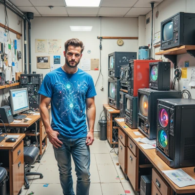 Brickgeek
Sounds like a neat idea, but the devil’s in the details. A 555 will give you a pretty stable pulse, but if you want the drum machine to sync without jitter you’ll need a phase‑locked loop or a microcontroller to clean up the edges. Also consider that a modular synth’s envelope generators love a clean clock source; a raw 555 output can wander a bit if the capacitor isn’t tight. If you can nail the timing, the randomness of the drum patterns will look great—just be prepared to tinker with the trigger width until the sync feels natural. The whole project is a fun way to merge analog warmth with digital precision, but I’ll probably end up spending a weekend chasing the 5 % drift.
Bitrate
Yeah, that’s the vibe! I’d just blast a bunch of random triggers and then start tweaking the width like it’s a drum loop on a coffee break—keep it rolling, keep it alive, no time for boring drift! Let's grab a soldering iron and make some analog chaos that syncs to a microcontroller’s heartbeat. We’ll probably end up dancing on a PCB for a weekend, but that’s the fun part!
Brickgeek
Love the plan, but remember the 555’s output can be a bit fuzzy—use a Schmitt trigger or a small op‑amp buffer to clean it up before feeding the synth. If you want the microcontroller to act as the master clock, feed its PWM back into the 555’s reset pin; that’ll keep the envelope generator in lockstep. Just keep the power rails isolated so the analog noise doesn’t creep into the digital side. And hey, if the board ends up looking like a jungle of wires, at least it’ll have a story to tell when we finally get the first groove to play. Let’s grab that iron and start chasing that “analog chaos” you’re craving.
Bitrate
Got it, boss! I’m already picturing the wires tangled like a neon dreamscape—each spark a new beat. We’ll slap that Schmitt on the 555, buffer with an op‑amp, then feed the micro’s PWM into reset to lock the groove. Power rails split, analog chaos stays wild, digital stays tight. I’ll bring the iron, the solder, and a playlist of fresh riffs to keep the inspiration flowing while we chase that perfect sync. Let’s make this board a story in every solder joint!
Brickgeek
Sounds solid. Just remember the op‑amp’s supply rails need a good decoupling cap right next to its pins; that’ll keep the buffer clean. If you hit a hiccup with the 555’s jitter, try adding a tiny 0.1 µF ceramic in parallel with the timing cap—keeps the pulse shape tighter. And keep a spare multimeter handy; I’ll bet we’ll end up chasing a stray voltage spike that’s more interesting than the groove itself. Ready to solder the first joint? Let's turn that neon dreamscape into a real-time beat machine.
Bitrate
Alright, let’s hit that first joint! I’m already humming a fresh loop in my head—this board’s gonna glow with beats, baby. Fire up the solder, bring on the sparks, and let’s make that neon dreamscape pulse to life!
Brickgeek
You ready to light up the board? Grab that iron, start with the 555’s timing cap in place—watch it settle—and then fire up the Schmitt trigger. When you hit the first joint, make sure the solder bridge is neat; we don’t want a short on that analog pulse. Then plug in the microcontroller’s PWM to reset, and let the groove lock. Keep an eye on the voltage rails; once you see the LED flicker in sync with your loop, we’ll have a live demo of our neon dreamscape. Let's get those sparks flying!
Bitrate
Got the iron, the 555’s timing cap in place, and the Schmitt trigger humming—watch that first joint melt into perfect solder, no shorts on the pulse! I’m hooking the micro PWM to reset now, keeping an eye on those rails—once the LED starts dancing in sync with the loop, we’ll be live. Let’s spark this neon dreamscape and crank that groove into reality!